Structural and Seismic Strengthening of Existing Buildings: Methods and How to Choose
Structural strengthening is what you do when an existing building cannot safely carry the loads it will face. Seismic strengthening is the part of that work aimed at earthquakes. Both start the same way: an engineer finds out what the building actually has, compares it with what it needs, and closes the gap with the least disruptive method that works.
This guide is for owners and owner's representatives. It explains what each common technique fixes, where it falls short and how a retrofit moves from assessment to handover. It will not replace your engineer, but it should help you ask better questions.
Structural strengthening and seismic strengthening: what the terms mean
Structural strengthening is the broad term. It covers any work that raises the capacity of a structure, whether the reason is heavier equipment, corrosion, fire damage or earthquakes.
Seismic strengthening, also called seismic retrofit or seismic rehabilitation, is the earthquake case. Earthquakes load a building sideways and in cycles, so the fixes focus on lateral strength, deformation capacity and a continuous load path to the soil. A building can carry its floors well for decades and still be unsafe in an earthquake.
The two overlap. A new shear wall added for earthquakes usually needs a new foundation, which is ordinary structural strengthening, so most schemes mix both.
When does a building need strengthening? Assessment comes first
Typical triggers are a change of use, visible damage, a local mandate or an owner who knows the building predates modern seismic design. Whatever the trigger, the method comes last. The first step is a seismic assessment against the standard that applies where the building stands.
United States: ASCE/SEI 41
ASCE/SEI 41, Seismic Evaluation and Retrofit of Existing Buildings, is the national consensus standard. Its current edition was published in 2023. It uses three tiers: a Tier 1 screening, a Tier 2 evaluation that targets known deficiencies for common building types, and a Tier 3 systematic evaluation that can be applied to any building. Performance levels such as Immediate Occupancy, Life Safety and Collapse Prevention are each paired with a hazard level. For ordinary buildings (Risk Category I and II), the 2017 edition's Basic Performance Objective for Existing Buildings pairs Life Safety with the BSE 1E hazard and Collapse Prevention with the stronger BSE 2E hazard. The 2023 edition also points to ACI 369.1 for existing concrete buildings and AISC 342 for existing steel buildings, according to ASCE's summary of the update.
Europe: Eurocode 8 Part 3
EN 1998 Part 3, Assessment and retrofitting of buildings, checks three limit states: Near Collapse, Significant Damage and Damage Limitation. Its recommended return periods are 2,475, 475 and 225 years, though national annexes may choose different values. It also ties the analysis to what the engineer actually knows: material strengths are divided by a confidence factor of 1.35, 1.20 or 1.0 depending on which of three knowledge levels is reached (Pinto, JRC Eurocodes training). For an owner the lesson is simple: more testing can mean a smaller retrofit, because the engineer no longer has to assume the worst.
Turkey: TBDY 2018 Chapter 15
In Turkey the assessment and strengthening of existing buildings sits in Chapter 15 of the Türkiye Bina Deprem Yönetmeliği (TBDY 2018). It defines limited and comprehensive knowledge levels and names the accepted methods for concrete buildings, from column jacketing to new shear walls and mass reduction. It also separates member strengthening from system strengthening, a distinction worth keeping in mind below.
Two ways to fix a building: raise capacity or reduce demand
FEMA 547, the federal guide to seismic rehabilitation techniques, sorts the options into a few classes (FEMA 547, Chapter 3). Most schemes add new elements to gain strength or stiffness, enhance existing elements so they can deform further without failing, or improve connections so the load path holds together. A smaller group of schemes works on the demand side instead: removing mass, adding damping or isolating the building from the ground.
Capacity methods make the building tougher, but it still feels the full shaking, and contents and finishes take the hit. Demand methods change what the building feels. Many good retrofits combine the two.
Structural strengthening methods, one by one
1. Reinforced concrete jacketing
What it fixes. New reinforced concrete is cast around an existing column, beam or wall. The larger section gains shear strength, axial capacity and confinement, and with new bars carried through the slabs it can gain flexural capacity too. In tests reported in FEMA 547 (Alcocer and Jirsa, 1991), jacketed columns produced strong column, weak beam behavior with peak strength more than four times that of the original assembly.
Pros and limits. It uses ordinary materials and contractors and can fix several deficiencies at once. The price is size: TBDY 2018 sets a minimum jacket thickness of 100 mm (about 4 inches), and the stiffer member attracts more seismic force. Everything depends on the new concrete working with the old, so the surface must be roughened and enough dowels must be provided. FEMA 547 points to fib Bulletin 24 for the research on concrete jackets. TBDY reduces the calculated strength and stiffness of an enlarged column by a factor of 0.9.
Disruption. High. FEMA 547 describes formwork, holes through slabs and concrete placement in tight spaces, with significant cost and disruption.
2. Steel jacketing
What it fixes. Steel angles and plates welded around a column add confinement and shear strength and can clamp a weak lap splice. TBDY 2018 describes four corner angles tied with horizontal plates. The jacket raises flexural and axial capacity only if the angles run continuously between floors and bear on the slabs through cap plates, and a calculation must show this.
Pros and limits. The jacket stays thin. It needs field welding and a grouted gap, and on long rectangular columns it loses effectiveness; FEMA 547 notes that Caltrans uses elliptical jackets in those cases. Exposed steel needs fire and corrosion protection.
Disruption. Moderate. Little wet work, but heavy plates and welding inside the building.
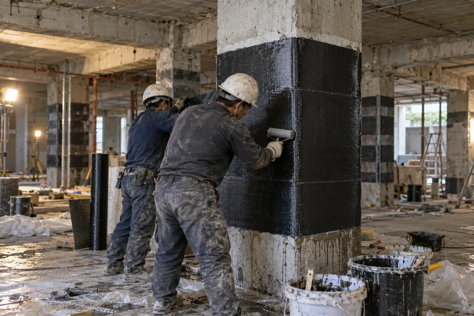
3. Fiber reinforced polymer wrapping (CFRP and GFRP)
What it fixes. Carbon (CFRP) or glass (GFRP) fiber sheets are bonded to concrete with epoxy. Around a column they confine the concrete, add shear strength and help a short lap splice. Along a beam or slab they add flexural or shear capacity. The US guide is ACI 440.2R, reissued in 2023 as ACI PRC 440.2 (2023) with a chapter on seismic strengthening. Confinement models such as Lam and Teng (2003) describe the gain in concrete behavior.
Pros and limits. The wrap barely changes member size and does not corrode. TBDY 2018 is clear that column wrapping does not raise flexural capacity, and it requires full wrapping, at least 200 mm of overlap and corners rounded to a radius of at least 30 mm. ACI 440.2R sets strengthening limits so the bare member can still carry a defined load if the FRP is lost to fire or vandalism. FRP adds little global stiffness, so it rarely fixes a building that drifts too much. It is also not cheap. FEMA 547 calls FRP overlays relatively expensive compared with steel and concrete, and says their advantage is in limited access and minimal disruption.
Disruption. Low to moderate. No formwork, and the work moves floor by floor.
4. New shear walls
What it fixes. Many older concrete frames lack lateral strength and stiffness. A new wall inside a frame bay or alongside the frame addresses that directly. TBDY 2018 requires added walls to run continuously from a new foundation, with anchor bars of at least 16 mm diameter, embedded at least ten bar diameters and spaced no more than 400 mm apart.
Pros and limits. Walls add a large amount of stiffness and take load off existing columns. They cost floor space and daylight, and they need foundations. The connection to the slab above decides whether the wall works, because it must transfer shear without slipping. Shotcrete walls are generally cheaper than walls cast in place because one side of the formwork disappears (FEMA 547).
Disruption. High. FEMA 547 says new walls can be very disruptive: drilling dowels sends noise and vibration through the whole structure, the work is wet, and footings mean excavation indoors.
5. Steel bracing
What it fixes. Diagonal steel braces inside frame bays add lateral strength and stiffness. Concentric braces are the stiffer option. Eccentric braces leave a short link that yields and absorbs energy. New steel systems follow AISC 341.
Pros and limits. Braces are lighter than walls and keep more openings. They concentrate force at their ends, so connections, adjacent columns and the footings under braced bays all need checking.
Disruption. Moderate. FEMA 547 says bracing generally costs and disrupts less than shear walls, with fewer penetrations and no wet work, though cutting and drilling still make occupancy difficult.
6. Buckling restrained braces
What it fixes. A steel core sits inside a casing, often a grout filled steel tube, separated so the two do not bond. The casing stops buckling, so the core yields in both tension and compression and dissipates energy both ways.
Pros and limits. Behavior is stable and predictable. FEMA 547 notes these braces are typically used in new buildings but have been used successfully in existing ones. They are proprietary and, under AISC 341, backed by qualification testing, so the supplier shapes the design early (Sabelli, AISC).
Disruption. Similar to conventional bracing.
7. Dampers: viscous and friction
What it fixes. Fluid viscous dampers resist in proportion to velocity; friction dampers slip at a set force. FEMA 547 says added damping reduces displacement, acceleration and interstory drift, and is most relevant in flexible buildings such as steel or concrete moment frames.
Pros and limits. Dampers reduce demand, which helps contents as well as structure, but they impose local forces the frame and foundation must carry. Analysis usually means nonlinear time history work, and most devices are proprietary. FEMA 547 calls added damping a relatively unusual retrofit strategy.
Disruption. Similar to adding a braced frame, since dampers usually sit in new brace lines.
8. Base isolation retrofit
What it fixes. Flexible bearings between the building and its foundation lengthen its period, typically to about 2 to 4 seconds according to FEMA 547, so far less ground motion reaches the structure and its contents.
Pros and limits. Most of the work happens at one level, so historic interiors and upper floors can stay largely untouched. FEMA 547 lists the limits: it is usually a very expensive strategy, buildings on very soft soil and very tall flexible buildings may gain little, and it needs a moat, flexible utility crossings, new structure above the isolators and a foundation below them. Retrofit cost is set building by building. For context only, in Turkish new construction isolation is reported to add roughly 10 to 15 percent to the cost of the structural frame (TRT Haber, Anadolu Agency). Our guide to base isolation retrofit for existing buildings covers the site process, and can isolators be added to an existing building answers the feasibility question.
Disruption. Heavy but concentrated at or below the lowest level.
9. Foundation strengthening and underpinning
What it fixes. New walls and braces deliver large forces to the ground and often need new or enlarged footings. Existing foundations may lack uplift or bearing capacity, or sit on soil prone to liquefaction. Tools include enlarged footings, grade beams, mats, micropiles, drilled piers and ground improvement by grouting. Underpinning digs under an existing footing in short alternating pits so the soil never loses support all at once (FEMA 547, Chapter 23).
Pros and limits. FEMA 547 warns that foundation work in existing buildings is expensive and that its need should be proven by careful analysis. Access limits the tools: drill rigs made for use inside buildings often need 9 to 12 feet of clear height. Micropiles are common because they bring less noise and vibration.
Disruption. High at ground level.
10. Connection strengthening
What it fixes. Walls pull away from floors, and floors lack collectors to feed load into walls. In houses, the whole building can slide off its foundation. Ties, collectors and anchors give the building a continuous load path. FEMA 547 treats connection work as its own class of measure and notes that wall to floor ties often have to be supplied whatever else is added.
Pros and limits. It hides in ceilings and floors, so it is easy to underrate. On its own it will not fix a building that lacks strength.
Disruption. Low to moderate.
11. Mass reduction
What it fixes. Less mass means less inertial force. TBDY 2018 lists removing upper floors, replacing a heavy roof, bringing rooftop water tanks to the ground and swapping heavy balconies, parapets, partitions and cladding for lighter ones.
Pros and limits. FEMA 547 warns the benefit is not proportional. Removing upper stories shortens the period, which can raise spectral acceleration enough that base shear barely falls or even rises.
Disruption. Depends on scope; removed floors are gone for good.
Strengthening methods compared
The table summarizes the sections above. Disruption is qualitative and drawn from FEMA 547. Actual numbers for any building come from its own analysis.
| Method | What it improves | Disruption | Typical use |
|---|---|---|---|
| Reinforced concrete jacketing | Member shear, axial and flexural capacity, confinement | High | Weak concrete columns where openings must stay |
| Steel jacketing | Confinement, shear, lap splices | Moderate | Columns where space is tight |
| FRP wrapping (CFRP, GFRP) | Confinement, shear, lap splices; flexure when bonded along members | Low to moderate | Local deficiencies, occupied buildings |
| New shear walls | Global lateral strength and stiffness | High | Concrete frames with a weak lateral system |
| Steel bracing | Global lateral strength and stiffness | Moderate | Frames where walls would block too much |
| Buckling restrained braces | Strength, stiffness and energy dissipation | Moderate | Braced schemes needing predictable yielding |
| Viscous or friction dampers | Energy dissipation, lower drift and acceleration | Moderate | Flexible moment frame buildings |
| Base isolation retrofit | Lower demand on the whole building and its contents | High at the base, low above | Hospitals, heritage buildings, valuable contents |
| Foundation strengthening | Bearing, uplift and ground hazard resistance | High at ground level | Under new walls and braces, poor soils |
| Connection strengthening | Continuous load path | Low to moderate | Almost every retrofit |
| Mass reduction | Lower inertial force, when the period shift allows | Varies | Heavy roofs, tanks, cladding |
How to choose a strengthening method
Four questions decide the method. Answer them before anyone prices a scheme.
What performance do you need? A building that only has to avoid collapse and one that must reopen the day after an earthquake are different projects; in ASCE/SEI 41 terms, Life Safety versus Immediate Occupancy. A hospital pushes you toward demand reduction. An ordinary apartment block can often reach its target with walls and local work.
Can people stay during the works? If the building must stay in use, favor dry, local work that can be phased, such as FRP, steel jackets and bracing. Isolation keeps the heavy work at the base. New walls and concrete jackets are the hardest to live with.
What kind of building is it? FEMA 547 organizes its catalogue by building type because a nonductile concrete frame and an unreinforced masonry building fail in different ways. Flexible frames suit dampers. Heavy masonry landmarks have been isolated. Wood houses usually need anchorage and bracing at the foundation.
Can the work be staged? If budget or occupancy rules out one large project, FEMA P 420 describes incremental rehabilitation: fixing the worst deficiencies first and folding the rest into planned maintenance and capital work. The full scheme should still be designed up front so each stage fits the next.
The design and approval process
- Assessment. Collect drawings, survey the building, test materials and investigate the foundation and soil. The knowledge level you reach changes the result, as the Eurocode confidence factors show.
- Concept. Compare two or three schemes against the same performance objective, disruption limits and budget. This is the owner's best moment to influence cost.
- Design. The strengthened building is checked with the same standard used for the assessment. TBDY 2018 requires exactly that, while new members follow the rules for new construction.
- Peer review. For isolation, dampers and other complex schemes, independent review of the design is standard practice and often required by the building department.
- Permits. Submit the assessment, design and calculations to the authority having jurisdiction. Expect questions on temporary works and phasing.
- Construction QA and QC. Special inspection of anchors, dowels, welds and FRP application; pull tests and cores where the design depends on bond.
- Testing and records. Keep material tests, product qualification reports and as built drawings. Isolators and buckling restrained braces are backed by prototype or qualification tests, and damper properties come from the manufacturer's test data.
Common mistakes owners make
Picking the method before the assessment. A contractor who sells FRP will propose FRP. The assessment should tell you what is wrong first.
Strengthening members while ignoring the system. Wrapping every column does not help a building whose real problem is lateral stiffness. TBDY 2018 treats member and system strengthening as separate categories.
Forgetting where the force goes. Jackets, walls and braces attract load. The footing under a new wall and its connection to the slab above then have to carry it.
Saving money on investigation. Little testing means conservative assumptions, and those mean a bigger retrofit.
Treating nonstructural damage as someone else's problem. After the 2023 Kahramanmaraş earthquakes, reconnaissance of eleven isolated hospitals found no structural damage, and the nonstructural damage that did occur traced back to poor detailing, workmanship and blocked movement gaps (TASI and DİD reconnaissance report). Ceilings, equipment and gaps need their own design.
Structural strengthening for your home
Houses follow the same logic at smaller scale. For wood frame homes on raised foundations, the typical retrofit bolts the house to its foundation and braces the short cripple walls in the crawl space, so the house cannot slide or topple off. California's Earthquake Brace + Bolt program supports exactly this work on older raised foundation houses (CRMP), and FEMA P 1100 gives engineered and prescriptive methods for one and two family dwellings. Concrete and masonry homes need an engineer's assessment like any other building. For a homeowner's view of what makes a house perform well, read our guide to the earthquake resistant home.
Projects worth knowing
USC University Hospital, Los Angeles. It is not a retrofit, but it is the clearest early evidence of what isolation delivers. Built isolated and completed in 1991, it was shaken by the 1994 Northridge earthquake; its instruments recorded superstructure drift of about a tenth of the allowable and no structural or contents damage (Celebi, 1996, USGS).
Salt Lake City and County Building, Utah. An unreinforced masonry landmark set on 443 lead rubber isolators above its existing footings, believed by its engineers to be the first historic structure retrofitted with base isolation (OSTI record).
New Zealand Parliament Buildings, Wellington. From 1992, Parliament House and the Parliamentary Library were cut from their foundations and set on 417 lead rubber isolators, avoiding the intrusive shear walls a conventional scheme would have needed (New Zealand Parliament).
Frequently Asked Questions
What is the difference between structural strengthening and seismic strengthening?
Structural strengthening is any work that raises the capacity of a structure, for gravity, wind or earthquake loads. Seismic strengthening is the earthquake case, focused on lateral strength, deformation capacity and a continuous load path. Most retrofit projects include some of each.
Which seismic strengthening technique is best?
There is no single best technique. Shear walls and braces fix a weak lateral system, jackets and fiber reinforced polymer wraps fix weak members, and dampers or isolation reduce demand on the whole building. The right choice follows from the assessment and the performance you need.
Do I need an engineering assessment before choosing a strengthening method?
Yes. The method should come out of an assessment against a recognized standard, such as ASCE/SEI 41 in the United States, Eurocode 8 Part 3 in Europe or Chapter 15 of TBDY 2018 in Turkey. Better testing often leads to a smaller retrofit, because the engineer can use measured properties instead of conservative assumptions.
Can a building stay occupied during strengthening works?
Often partly. Dry, local methods such as fiber reinforced polymer wrapping and steel bracing are the easiest to phase around occupants, and base isolation keeps the heavy work at the lowest level. New concrete walls and jackets are the most disruptive.
Is fiber reinforced polymer wrapping enough on its own?
Only when the problem is local, such as column confinement, shear or lap splices. Wrapping adds little global stiffness and, under TBDY 2018, does not raise a column's flexural capacity. A building that drifts too much usually needs walls, braces, dampers or isolation, with wrapping for the remaining local deficiencies.
Is base isolation a strengthening method?
Strictly, it reduces demand rather than adding strength. Flexible bearings under the building lengthen its period so less of the ground motion reaches the structure and its contents. It is usually the most expensive option and suits hospitals and heritage buildings best.
How much does structural strengthening cost?
It depends on the building, the performance objective and whether it stays in use. Cost figures per unit of floor area mislead, because two buildings of the same size can need very different schemes. A concept study that prices two or three options against the same objective is the reliable way to get a number.
If you want this assessed for your own building, book a 30 or 60 minute online consultation and we will review your structure and which option fits it. More on how we work as an independent owner's advisor is on our consulting page.
Sources & References
- ASCE, ASCE/SEI 41 (2023 edition), Seismic Evaluation and Retrofit of Existing Buildings, 2023.
- ASCE Civil Engineering Source, summary of updates in the 2023 edition of ASCE 41, December 2023.
- Performance objectives for evaluation and retrofit, ASCE 41 (2017 edition) (UpCodes).
- FEMA 547, Techniques for the Seismic Rehabilitation of Existing Buildings, 2006.
- FEMA P 420, Engineering Guideline for Incremental Seismic Rehabilitation, 2009.
- FEMA P 1100, Vulnerability Based Seismic Assessment and Retrofit of One and Two Family Dwellings, 2019.
- American Concrete Institute, ACI PRC 440.2 (2023), Design and Construction of Externally Bonded FRP Systems for Strengthening Concrete Structures, Guide (supersedes ACI 440.2R, 2017 edition).
- American Concrete Institute, ACI CODE 369.1 (2022), Seismic Evaluation and Retrofit of Existing Concrete Buildings.
- AISC, ANSI/AISC 342 (2022), Seismic Provisions for Evaluation and Retrofit of Existing Structural Steel Buildings.
- Sabelli, R., Buckling Restrained Braced Frames, AISC.
- Pinto, P., Eurocode 8 Part 3: Assessment and retrofitting of buildings, JRC Eurocodes training, Lisbon, 2011 (on EN 1998 Part 3 (2005)).
- fib Bulletin 24, Seismic assessment and retrofit of reinforced concrete buildings, 2003.
- Türkiye Bina Deprem Yönetmeliği (TBDY 2018), Chapter 15, Resmî Gazete, 18 March 2018.
- Lam, L. and Teng, J.G., Design oriented stress strain model for FRP confined concrete, Construction and Building Materials 17, 2003.
- Celebi, M., Successful performance of a base isolated hospital building during the 17 January 1994 Northridge earthquake, 1996.
- Seismic isolation retrofitting of the Salt Lake City and County Building, 1991 (OSTI record).
- New Zealand Parliament, The earth may move, but Parliament stays put (fact sheet).
- TASI and Deprem İzolasyonu Derneği, Kahramanmaraş Earthquakes Observation Report, May 2023.
- California Residential Mitigation Program, The Earthquake Brace + Bolt Retrofit.
- TRT Haber, interview with Dr. Cüneyt Tüzün on seismic isolator cost, January 2020.
- Anadolu Agency, report quoting Prof. Dr. Beyhan Bayhan and Prof. Dr. Gökhan Özdemir on isolation cost, May 2025.
Similar Articles
Base Isolation Retrofit for Existing Buildings: Process and Cost
How a base isolation retrofit works step by step: feasibility, design, construction sequence, real project examples, cost...
Read articleRetrofit GuideCan Seismic Isolators Be Added to Existing Buildings?
Complete guide to retrofitting existing buildings with seismic isolators. Learn how base isolation retrofits work, which...
Read articleStructural DurabilityHow Long Does a Reinforced Concrete Building Last?
Concrete buildings do not expire, they corrode at a rate set by cover, mix design and exposure. What governs service life, how...
Read article